Eddyfi Technologies provides the highest performance non-destructive testing (NDT) inspection technologies in the world, helping OEMs, asset owners and service companies enhance productivity, save lives, and protect the environment. We focus on offering advanced phased array ultrasonic testing, eddy current array, and other ultrasonic and electromagnetic equipment including instruments, sensors, software and robotic solutions to key industries such as aerospace, energy, mining, power generation, and transportation.
About UsFeatured Blog Post
The Low-Down on Enhancing Boiler Tube Inspection Efficiency with Phased Array UT Technology
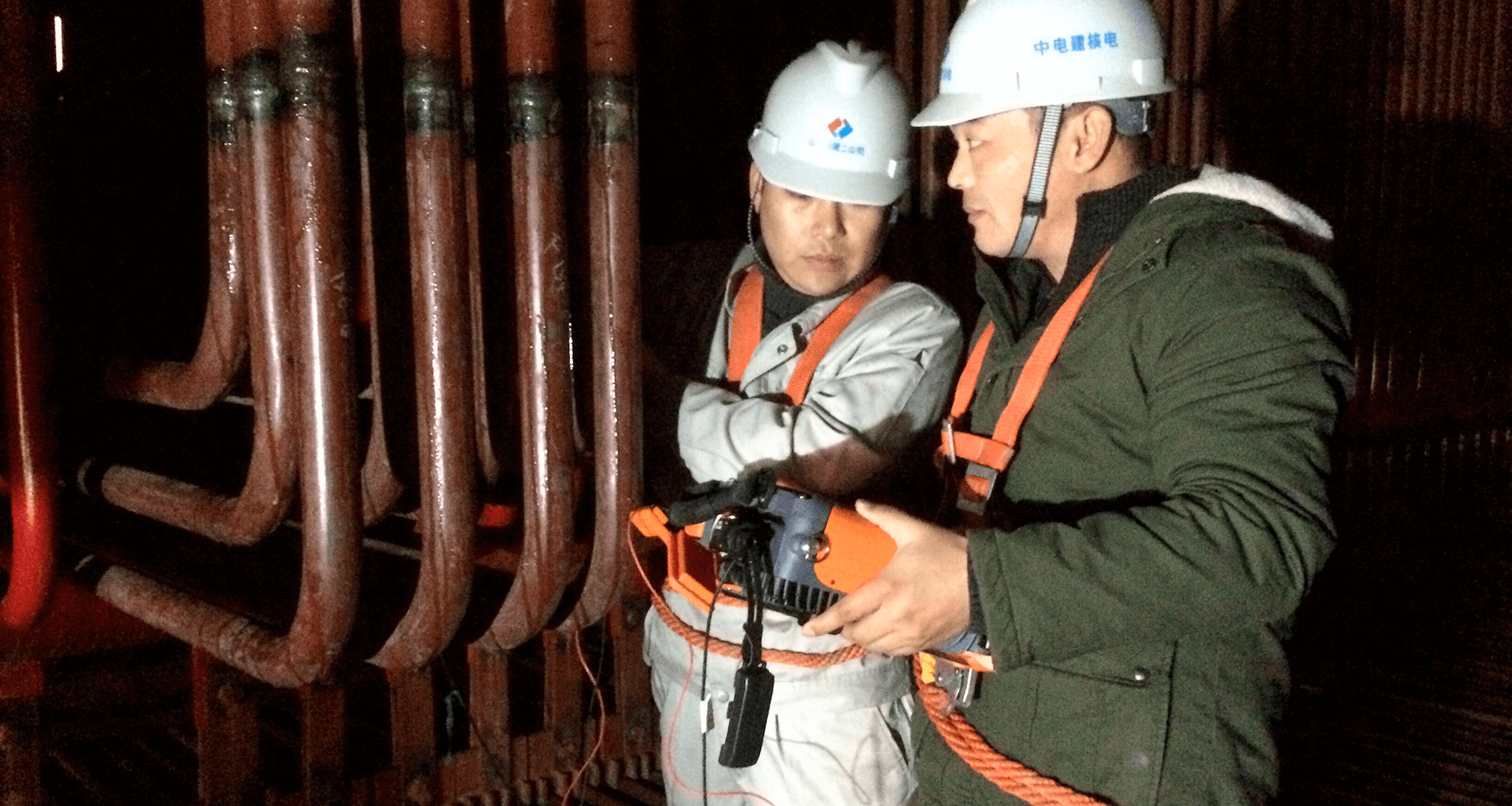
Encoded phased array ultrasonic testing (PAUT) technology can be a reliable and efficient alternative to radiography for boiler tube weld examination. However, several challenges arise when attempting to perform inspections in the tight environment inside of a boiler. The major concern with boiler tubes is the low clearance between pipes. The other complexity is the small wall thickness of the pipes, combined with a variety of diameters, and the presence of the weld caps. To tackle the challenges listed above, a complete phased array UT inspection solution requires both low-profile PAUT probes and wedges, and a low-profile scanner.
Latest Blog Posts
-
Thinking Big, Inspecting Small: Eddyfi’s Expertise in Small-Diameter Stainless-Steel Welds
April 23, 2024
-
How To Better Detect Wet Hydrogen Sulfide (H2S) Damage
April 9, 2024
-
Introducing TubePro™ 6: Streamlined Workflows and Enhanced Performance to Elevate Heat Exchanger Tubing Inspections
April 2, 2024
Latest Application Note
Inspecting Stainless Steel and Dissimilar Metal Welds with FMC and PWI
All Application NotesLatest News
March 27, 2024
Eddyfi Technologies Launches TubePro 6: Revolutionizing Heat Exchanger Tubing Inspections with Enhanced Reporting Capabilities

Upcoming Event
Control 2024
Control, the leading international trade fair for quality assurance, creates added value in terms of information, communication and business by presenting the latest technologies in metrology, materials testing, analytical equipment, optoelectronics and QA systems for quality assurance. Industrial weighing and counting technology as well as sensor technology complete the program. Control works very intensively with the pioneering institutions in the industry.
Other Featured Events
-
ILTA 2024
May 6, 2024
Join Eddyfi Technologies at ILTA 2024 from May 6-8, 2024, in Houston, TX! Celebrating ILTA's 50th Anniversary, we're proud to showcase the most advanced NDT solutions for OEMs, asset owners, and service companies. With a rich history of advocacy and industry leadership, ILTA continues to shape the liquid terminal landscape. Stop by to explore our comprehensive portfolio of NDT sensors, instruments, software, and robotic solutions, empowering industries like aerospace, energy, and power generation. Don't miss this opportunity to connect, innovate, and celebrate with us at ILTA 2024!
-
DGZFP Annual Conference 2024
May 6, 2024
Join us at the DGZfP-Jahrestagung, the premier gathering of the non-destructive testing (NDT) community, where groundbreaking advancements meet collaborative exchange. As the leading provider of cutting-edge NDT inspection technologies, Eddyfi Technologies proudly announces its participation in this year's event. This year's conference offers a prime opportunity to delve into the latest developments in NDT research, development, and application. From aerospace to oil & gas, and power generation, our diversified portfolio of instruments, sensors, software, and robotic solutions is revolutionizing inspection practices worldwide.
-
Abendi 15th NDT and Inspection Conference
May 16, 2024
Breaking Boundaries: Eddyfi Technologies at the 15th Regional NDT and Inspection Conference Join us on May 16th and 17th, 2024, at the prestigious Hotel Royal Macaé Palace in the vibrant city of Macaé, Rio de Janeiro, for the 15th Regional NDT and Inspection Conference. This annual gathering, focused on the offshore sector, promises to be an enriching experience, featuring presentations and discussions led by industry experts. It's an unparalleled opportunity to exchange insights, forge valuable connections, and explore emerging trends in Non-Destructive Testing (NDT) and Inspection. Eddyfi Technologies, a global leader in advanced NDT solutions, is excited to be part of this dynamic event. With a commitment to innovation and excellence, we offer a diverse range of NDT instruments, software, and robotic solutions designed to meet the evolving needs of the industry.